Topographical documentation of the project – Interim surveys
The methodology followed by XYZ covers both the needs for Monitoring and for the Verification and Documentation of each relevant Report that needs to be prepared.
The key feature of the methodology is the use of the single project background. The Initial Project Background measured is constantly updated with changes that occur in the project.
The 2.5D (2.5 dimensional) topographic background (horizontal plan with elevations) is entered into a GIS database established for this purpose. This plan is the basic background of the database. All other measurements and checks to be made and the instruments documenting them will be reported and located in this background.
| Background status | Status of the project | Action | Database | Documentation | ||||
| Original Background | Rev.0 | Initial Status | Original Imprint | Establishment of the GIS Base | Topographical Chart 1:500 or 1:200 where required (2,5D Drawings) | 3D Cloud Point Meter (or 3D Drawings)+ 360⁰High Resolution Photo | Measuring orthophotographs | Depth Metrics |
| Geodetic Stations or Geodetic Satellite Receivers (GNSS) | Terrestrial Laser Scanner Scan&Drive | UAS for topview or Drone for sideview | ||||||
| Position/ Altitude inaccuracies (XY / Z) | ||||||||
| <2cm / 2cm ή <1cm /1,5cm | <1cm /1cm | <5cm /10cm | <5cm /10cm | |||||
| Terrain Hand Over | Rev.1 | Changes to deliver part of the Land to a Contractor | Mapping of the Department to be delivered | Updating the GIS Base | Join Syrvey | Topografic Baseline | ||
| Updated Background “As Is” | Rev.1+ν | Project in progress | Imprints Checks | Updating the GIS Base | Survey Report / Audit and Deviation Plans | Topografic Baseline | ||
| As Built Drawings | Final Rev. | Completion of each project | Final Imprint | Base Completion | Control and Deviation Plans | Final Imprint | Final Imprint | Final Imprint |

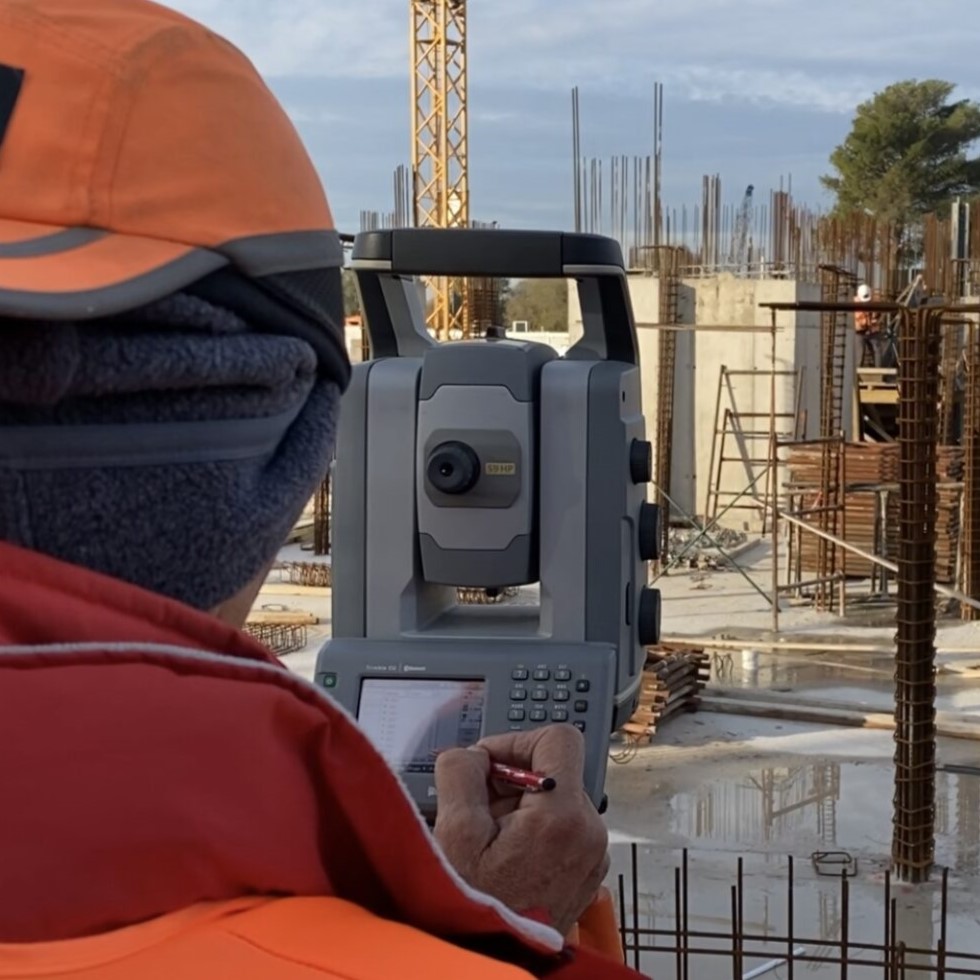
Topographic measurements
These measurements are made purely by geodetic methods:
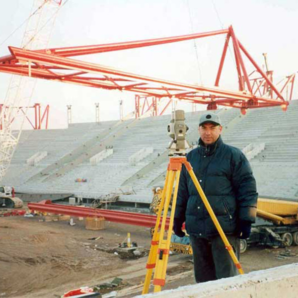
- MAPPING WITH GEODETIC GNSS RECEIVERS
- MAPPING WITH ROBOTIC GEODETIC STATIONS
- MAPPING IN COMBINATION WITH A PRECISION DIGITAL SPATIAL COORDINATE SYSTEM
- THREE-DIMENSIONAL LASER SCANNING DENSIFICATION
For each new survey made and approved, the project’s Topographic Background is updated. The database shall be updated accordingly.
This procedure shall be followed in all phases of the project
- During the foundation of the individual building and technical works for the terrain hand-over certification
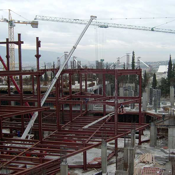
- During the development of the infrastructure projects
- During the development of underground network works
- Before the re-foundation of the works for the preparation of the as-built drawings
- Preparation of the corresponding as-built drawings of the completed projects
Join Survey
Connection to the Reference Network
Each reference in the Documentation and each individual survey or each individual pointing work for any purpose is linked as closely as possible to the As Built status of the Project and also to the design of the Project.
From each Trigonometric Datum, a connection can be made either to the new “Project Reference Network”, or to the EIA’ 87 which is connected to the Project’s and/or GIS’s Elevation Network.
It is inevitable that it is easy for any contractor to control with great precision his own work, the work of others, and the backgrounds he uses.
Both the location and elevations of existing engineering works are critical to be correct so that everyone who will be working on the project can be connected to them. It is after all easy to check the accuracy of their mapping.
In addition to the already captured data reported in the backgrounds:
- Buildings of all types (main buildings, auxiliary buildings, sheds, buildings under construction, ruins)
- Implemented boundaries (manhole walls, wire fences or other types of fencing)
- Terrain relief (toe and foot of slopes, terraces, embankments and slopes)
- Shafts and ditches, stream banks and beds, culverts
- Water reservoirs, boreholes, aqueducts, and
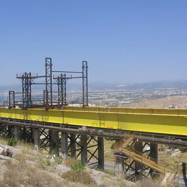
- Existing road network, bridges, retaining walls, curbs, islands, signs and other road equipment
- Railway tracks – tram lines
- Port structures, coastline and dredging
- Underground networks, services, cables, metallic pipes, storm drains
Also likely to need to be mapped:
Existing metal structures with complex three-dimensional shapes
Interiors of existing buildings that will not be removed and are likely to be used in the cladding
Specifications
The specifications for the topographical diagram intended for the issuance of Building Permit include briefly:
- Building Conditions, Land Use, existence of a G.P.S. (General Urban Plan), existence of a Z.O.E. (Housing Control Zone).
- Declaration on the existence of High or Medium Voltage Lines of the Public Power Corporation, Natural Gas, Electricity, Stream.
- Declaration of n. 651/1977.
- Declaration of Law No. 1337/83.
- Declaration of Law 2308/1995 of the National Land Registry.
- List of the coordinates of the vertices of the property, the vertices of existing buildings and future buildings in EAGS87
- The area of the property and the national cadastral code number (KAK) if available.
- The absolute heights of the tops of the property and the elevation curves.
- The complete and detailed survey of the property, with existing and future buildings with side dimensions.
- Redetermination of the Beach and Shoreline Lines in the case of Coastal Projects that for any reason related to shoreline development or where otherwise required
- Digital Signature.
The topographic plan is Digitally Signed according to N4409/2016. It is also checked, according to the rules of completeness, by the Greek Cadastre application and accompanied by a proof of EC control and will be ready for final submission for the issuance of a Proof of Electronic Chart Submission (e-Cadastre). In addition to the analogue paper copies (size A0 or A1), the deliverables include digital .pdf files
Initial Land Survey
Construction Verification
Our Projects


Contact us!
It is advisable to have someone with you who knows the property boundaries. It will be useful to have with you old topographic maps and anything related to the property (contracts, building permit plans, expropriation plans, classification deeds, cadastral maps, etc.). In case of a large area, wear comfortable clothes and shoes because we will need to walk the property’s contour to find its boundaries.
